Radar Cross-section measurement (RCS) is an essential part of commercial aircraft and helicopter detection. The VNA handheld product line has all the features and performance needed to simplify RCS measurements on the flight route and on-site.

Radar Cross-section (RCS) is a measurement of a target’s ability to reflect the radar signal in the direction of the receiving radar, which is a measurement of the ratio of the backscatter quantity per cubic angle unit in the direction of the radar target on the power density blocked by the target. RCS measurement aims to ensure that the designs of commercial companies in this field, military helicopters, and radar systems also achieve the desired quality and performance.

The accuracy of RCS measurement directly affects an aeronautical system’s safety and successful operation. In the military, stealth technology is used to reduce RCS and make it difficult to detect targets. In commercial aviation, a large RCS value is essential, from which the aviation radar system can easily detect, locate, and land safely. In practice, tactical jets typically have RCSs between 5 and 100 m2, and bombers typically have RCSs between 10 and 1000 m2. In contrast, stealth aircraft have RCS below 0.1 m2; some advanced designs can go down to 0.0002 m2.
The vector network analyzer (VNA) is the device of choice in RCS measurement applications because of its speed and accuracy in setting and measuring the S parameter. The enhanced VNA series enables the required performance allocation and features such as gating time domain measurement to simplify RCS measurement in the aircraft or on-site.
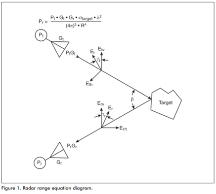
Radar range equation
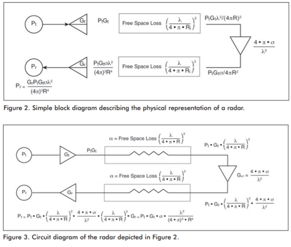
The radar system (Figure 2) transmits a signal pulse through a transmitting antenna with a gain of Gt. The signal amplitude at the output of the transmitting antenna is attenuated by free-space transmission. At the target, some of the power (backscatter) is reflected toward the radar. The ratio of the backscattered power to the incident power is the RCS of the target. Loss amplitude is due to free space. Therefore, the signal received by the receiving antenna has a gain Gr and is detected in the receiver.
The block diagram (Figure 2) describes the physical blocks of the radar. The equivalent circuit of the radar is shown in Figure 3. The transmitting and receiving antenna gains are characterized by the amplifiers, then the target.
Capacitors are characteristic of free space loss. The VNA system used to measure the S21 has the same schematic diagram as the radar system. It performs the response in the S21 frequency domain of the system when port 1 of VNA is connected to the transmitting antenna and port 2 is connected to the receiving antenna.
Although VNA is very popular for frequency domain measurement applications, the addition of time domain and Gating Time analysis features makes it possible to simulate radar pulse performance by eliminating reflection gaps that do not affect the target. A 12-month period of VNA’s error correction is to minimize system failures due to loss of coordination or leakage and to set the reference plane correctly.

Polarization
The polarization of the reflected signal’s electric field vector may differ from the polarization of the transmitted signal. The shape of the target affects the depolarization factor.
To perform precise depolarization, image the fully polarized matrix into the independent electric field’s horizontal and vertical field components. This leads to the requirement of two polarized transmitters and receivers. From the measurement, a polarization matrix will be generated to describe the polarization effect, thereby accurately performing depolarization.
VNA measurement
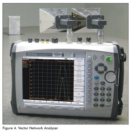
Figure 4 shows the measurement of the S parameter in the frequency domain. The frequency range of the measurement reflects the radar’s band (8.2 to 12.4 GHz, with an X-band WR-90 waveguide). VNA’s time domain feature transforms the frequency domain S parameter measurement into the time domain.

The basis of the transformation is Alias Free Range (AFR). The transformation is a circular function and iterates itself periodically out of its own time range, t=1/(frequency step magnitude). The frequency step magnitude is proportional to the sweep range and inversely proportional to the number of sweep points.
For example,
At band X, the scan range is 4GHz; there are 4001 scan points, AFR = 4000/4.0GHz= 1000 ns corresponding to 300 m of allowable deviation range. Within 300m of the 2-way distance, the target should be placed within 150m from VNA.
A typical helicopter RCS measurement configuration using VNA is shown in Figure 5. A transmitting antenna (connecting VNA port 1) and receiving antenna (connecting VNA port 2) are placed on the same plane. The measurement target consists of a helicopter placed on the flight path or over an area with few reflective objects.
Implementing S21 measurements (frequency domain) for VNA is done similarly to radar when configured. The coax output is connected to the waveguide-coaxial converter. Port 2 connects to the output of the waveguide receiver antenna.
Both antennas are connected as close as possible on the same horizontal or vertical plane. To construct the polarization matrix, both transmitting antennas must be able to rotate 90 degrees. The target must be located within a range less than AFR/2 but far away enough to ensure that the entire target is within the antenna’s beam.
RCS measurement
A 12-month calibration feature is implemented at the coax output to build a standard reference plane for RCS travel. The frequency domain S21(f) measurement is performed on the target range. The S parameter data is transformed over the distance domain S21(d) by performing a bandpass process. The system can be calibrated in RCS by measuring the known target in advance of the RCS and referencing all other targets to the known target.
The S21(f) measurement is taken as a standard measurement. The data of the S21 measurement is transformed in the time domain mode, and a suitable gate timing is set at the standard range. The amplitude S21(std) of the standard reflectance is calculated.
The value of the measurement reflects the RCS measurement. If the standard target is a sphere with an RCS of 1m2, then the RCS of the target is given by the equation:

The data unit is dBsm. Conversion formula: dBsm=10Log(RCSm2) (dB)
Our company always wishes to become a reliable partner and a leading supplier of equipment and solutions for the success of our customers. For more detailed information, please contact:
MITAS Hanoi Technology JSC
Address: 5th Floor, C’Land Building, No. 81 Le Duc Tho St., My Dinh 2 Ward, Nam Tu Liem Dist., Hanoi, Vietnam
Web: https://mitas.vn | Tel: (+84) 243 8585 111 | Email: sales@mitas.vn
The trust and support of our customers are a driving force and an invaluable asset to our company. We sincerely thank you./.
