Understanding the basics of analog signal analysis, signal forms and Huntron’s Error-Assessment Solutions.

1. Basics of analog signal analysis (ASA)
The Huntron Tracker outputs an AC sine wave signal with the correct limiting electric current to a component and displays the resulting electric current, voltage drop, and any phase shift on the device display. The current causes the vertical axis signal line deviation on the screen, while the voltage along the component causes the horizontal axis display signal deviation. The signal line that displays the results on the screen is called the analog display signal.
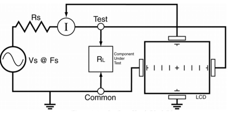
Understanding the ASA core circuit is the key to understanding how the analog display signal responds to the difference of component types. The ASA is sometimes referred to as a “V/I test” and since the constitutive current is a function of the impedance of the circuit, the displayed analog signal can be simulated by Ohm’s law.
V= IR (with V: voltage, I: current, and R: impedance)
The following figure shows a schematic diagram of the ASA core circuit. The sine wave signal source is the test signal source and is connected to an impedance voltage divider composed of Rs and RL. Resistive load, RL, is the impedance of the test device. RL is connected in series with an internal impedance source Rs; because Rs is fixed, both the voltage along the device being measured and the current through it are the sole function of RL.

Each test signal or range has three parameters: source voltage Vs, impedance Rs, and source frequency Fs. When using the ASA for error checking, the measuring object is selected for a range so that the display shows enough signal line information. The Huntron’s device can adjust the signal for easy reading and analysis by varying the parameter ranges. The source voltage Vs of the test signal can be used to increase or bypass the semiconductor switching and semiconductor cascade characteristics. Fs, or the frequency of the test signal source, can be used to increase or ignore the response coefficient (inductance and capacitance) of a component or a circuit node. Rs or source impedance is used to match the load impedance to be measured and provides a wealth of insight into the displayed signal curve.
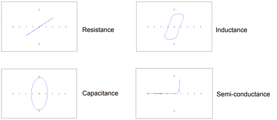
2. Signal form of four basic types of components
Including Resistance, Inductance, Capacitance, Semi Conductance with the following shape:

3. Huntron’s Error-Assessment Solution
Huntron’s solution allows to compare the signal form of two components of the same type with each other or components in the same position on two identical boards to easily detect which component is damaged and replace it.
In the figures shown below, the red signal line represents the signal of the faulty component, and the blue signal line shows the component operating normally.

With this reference method, Huntron’s solution can easily and intuitively detect and replace damaged elements in the circuit board, thereby providing a rapid repair process.

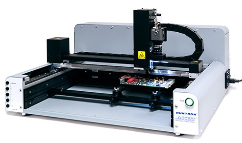
In addition to manual measuring equipment, Huntron also offers automated measuring systems for industrial-scale mass inspection. By storing the location and value of each component on the circuit board in normal operation as a comparison sample, for the following circuit tests of the same type, the device can automatically check and compare the value of each measured component with standard values to find fault locations many times faster than conventional circuit detection.
Our company always wishes to become a reliable partner and a leading supplier of equipment and solutions for the success of our customers. For more detailed information, please contact:
MITAS Hanoi Technology JSC
Address: 5th Floor, C’Land Building, No. 81 Le Duc Tho St., My Dinh 2 Ward, Nam Tu Liem Dist., Hanoi, Vietnam
Web: https://mitas.vn | Tel: (+84) 243 8585 111 | Email: sales@mitas.vn
The trust and support of our customers are a driving force and an invaluable asset to our company. We sincerely thank you./.
