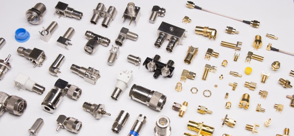
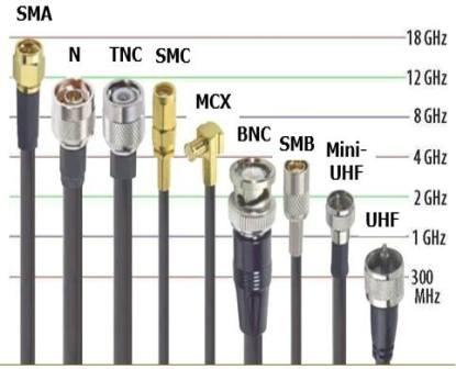
To be able to choose the suitable RF/microwave cable and adapter, the users are required to have an understanding of characteristics such as mechanical limitations and electrical characteristics and how they affect the application.

Cables and adapters are often left unnoticed by users in RF/microwave circuits and systems until they fail to perform as expected. Cables and adapters have quite simple functions in a system as they help transmit signals from one point to another. The better they are, the less they change signal characteristics such as amplitude, frequency, and phase and provide highly reliable connections to the rest of the system. However, the signal and applications are very wide, with a various range of high and low frequencies. Therefore, it is required to choose suitable cables, connectors, and connectors for the deployed application.
Choosing a cable is simply deciding to use between rigid and bendable cables or between semi-rigid and flexible coax. Semi-rigid coaxial cable has been used in RF/microwave systems for decades, with electrical efficiency advantages. As the name suggests, semi-rigid cables limit flexibility and maneuverability and often have to be cut and/or assembled with connectors to achieve the correct length in accordance with the mechanical requirements of the system. Although cable flexibility is limited, this type of coax cable typically has less insertion loss than flexible cables with similar diameter and size.
As a compromise between these two cables, manually crimped cables provide additional flexibility and can be bent to the required shape without any required tools. This cable type also achieves significantly improved insertion loss compared to flexible cables, but not as low as semi-rigid cables.
High-frequency cable is available from many different manufacturers with impedance characteristics of 50Ω and 75Ω, the latter commonly used in CATV cable television systems. Cable loss is usually defined as the loss per 100 feet of cable at a given frequency, and this parameter is essential when comparing cables to each other. All cables have an electrical length specification, which is the number of wavelengths per unit length of the cable at a given frequency.

The electrical length of a cable can also be considered as a phase delay, or the time it takes for a signal to travel from one end of the cable to the other compared to the time it takes for the signal to travel through the equivalent distance. According to the phase delay or propagation delay, the electrical length will often be defined as nanoseconds. The dielectric constant of the insulating material between the inner conductor and the outer sheath has a significant influence on the propagation delay, as it affects the signal propagation along the cable. To achieve low signal delay, insulating materials with a low dielectric constant are often used between the inner conductor and the outer conductor layer of high-frequency coaxial cables.
Several commercial suppliers of coax cables provide helpful application information in selecting cables and information on the performance effects of different cabling materials. One of the many important notes, such as “Solid Core and Braided Cables”, emphasizes the difference between a coaxial cable with a solid core and two types of braided cable (one with 7 fibers and one with 19). All three cables have SMA connectors and the test frequency ranges from DC to 18 GHz.
In manufacturing cables, it is necessary to maintain a consistent impedance level. To do this, with a cable with a solid core, it is essential to minimize the change in cable diameter both inside the core and outside the cable. For braided cored cables, the stranded cores must be organized to ensure small size tolerances to maintain the cable’s impedance. This is the difficulty in making stranded core cables that makes the production process of stranded core cables more expensive than solid core cables. However, braided core cable has the advantage of durability and flexibility.
From measurements at the same frequency, solid core cable has the lowest attenuation, followed by braided cable with 7 fibers and finally braided cable with 19 fibers (the most significant reduction). For each type of cable, signal attenuation also rises with increasing temperature. The solid core cable gives the best amplitude stability when bending, followed by braided cable with 19 strands, and finally, braided cable with 7 fibers (the worst amplitude stability in bending).
In terms of phase stability when bending, braided cables give the best results; 7-strand braided cables are least affected by phase changes when bent, followed by 19-strand braided cables and cored cables, especially susceptible to phase change when bending. In summary, in an application (e.g., in a test system), if a lot of bending is required, braided cables will be a better choice than solid cables, which tend to attenuate after 10000 inflection points.
Our company always wishes to become a reliable partner and a leading supplier of equipment and solutions for the success of our customers. For more detailed information, please contact:
MITAS Hanoi Technology JSC
Address: 5th Floor, C’Land Building, No. 81 Le Duc Tho St., My Dinh 2 Ward, Nam Tu Liem Dist., Hanoi, Vietnam
Web: https://mitas.vn | Tel: (+84) 243 8585 111 | Email: sales@mitas.vn
The trust and support of our customers are a driving force and an invaluable asset to our company. We sincerely thank you./.

