Antenna test and measurement is a common need in the telecommunications industry in general and high frequency in particular as this is one of the basic tasks of antenna theory.

1. General introduction
Antenna testing & measurement is a very common need in the telecommunications industry in general and high frequency in particular. This is one of the basic tasks in antenna theory. Antenna theory cannot be completed if the antenna under test (AUT) measurement cannot be achieved as desired. Basically, when doing this work, we want to test the basic theoretical parameters of the antenna such as gain, efficiency, impedance or VSWR, bandwidth, and polarization of the antenna. New technology combined with data processing software can also draw the antenna radiation pattern characterization diagram.
2. Antenna transmission theory
The antenna’s transmission space is divided into 3 areas: reactive, near-field and far-field.

The spatial region with a distance greater than 2D2/λ radiation is called the far-field region, in which D is the maximum length of the antenna. In this region, the beam shape does not change with distance; in other words, the measured radiation pattern characterization is determined.
The spatial region limited from λ to 2D2/ λ, is called the near-field region. The radiation pattern characterization of the antenna in this spatial region changes with distance, especially the shape of the beams. However, we can determine the equivalent radiation pattern characterization as the far-field region by mathematical transformations from near to far-field.
The spatial region limited from the reflecting surface of the antenna to a distance λ (1 times the wavelength) is called the ultra-near field region. In this space, the antenna’s radiation has a negative impact on the antenna itself. Therefore, the signal in this region is very noisy, unstable, and has many different beam shapes that change with distance. In other words, it is challenging to determine the antenna radiation pattern in this case.
For example, with a 1m diameter antenna operating at 10 GHz (λ = 3cm), the near-field region will extend to about 2/.03 = 66m.
Due to the changing characteristics of the signal wave according to the area and distance of the antenna, antenna test and measurement methods are also divided into different ways. In fact, antennas are the main elements used for long-distance communications, when wired transmission is difficult to meet the requirements. Therefore, testing antennas in the far-field region is the most necessary and realistic task. However, setting up an antenna test, measurement, and evaluation system in this region is not easy. Antenna test and measurement methods are divided into two types, which are near-field and far-field. With the near-field measurement method, the measuring distance is relatively small, so usually, the system can be explicitly installed in the home, also known as a measuring chamber or anechoic chamber. Testing in far-field regions often involves vast distances, especially large-sized, high-frequency antennas such as antennas of radar stations, aircraft antennas, antennas in high-frequency receiver and transmitter systems, etc.
3. General requirements and specifications
3.1. Required equipment for antenna testing and measurement
When using plane waves to test the antenna under test (AUT), we can consider using a source (transmitting) antenna with known characteristics and radiation patterns, affecting the antenna in the way of random fields. Required equipment includes the following:
- Transmitting antenna and signal generator: This antenna has known radiation used to transmit to the AUT.
- Receiver system: this part determines how much power the AUT receives.
- A positioning system: This system rotates the AUT, combined with the transmitting (source) antenna, giving a radiation curve as a function of the rotation angle.
The source antenna must ensure good operation at the frequency to be tested. This antenna must be polarized in advance and have a bandwidth suitable for the AUT antenna measurement range. The source antenna is usually a horn antenna or a dipole antenna with a parabolic reflecting surface.
The transmitter ensures stable power generation according to calculations. The output frequency must also be accurate and adjustable (ability to select and change the frequency range) and reasonably stable (low-frequency drift).
The receiver will be responsible for receiving and determining the power level of the signal received from the AUT. This receiver can be supplemented with low noise amplifiers to measure low power levels and extend the measurement range of the system.
The positioning system is used to steer and control the direction of the AUT. The essence of this method is to calculate the radiation graph of the AUT based on the results obtained from a function of the rotation angle value (e.g., spherical coordinates). The system will rotate the AUT in different directions and angles so that the transmitting antenna (source) can broadcast directly from many directions. Usually, the AUT will be turned and scanned 360 degrees in a spherical shape.
3.2. Measurement space
After having the measuring equipment, setting up a space to perform the antenna test is necessary. In theory, a measurement system can be deployed with such devices anywhere. However, in reality, this needs to be selected and calculated in detail because the antenna measurement requires a space unaffected by any signal or noise during the measurement process. Ideally, we need to perform this measurement in a space without any unwanted signal reflections or emissions during the measurement process. However, this is currently impossible. Therefore, the current solution chosen is to build a closed space, blocking all types of electromagnetic waves from unwanted radiation sources and making it capable of eliminating electromagnetic reflections in the implementation area. measurement.
It is called the Anechoic Chamber or Electromagnetic Wave Shielding Chamber.
It is easy to see that this method is very suitable for the near-field antenna measurement method because the measuring chamber area can only be built to a specific limit; it cannot be expanded too large, and it will encounter construction problems: construction and costs. Far-field measurement chambers are also deployed but are not as common as near-field.
* Anechoic Chamber (Electromagnetic Wave Shielding Chamber)
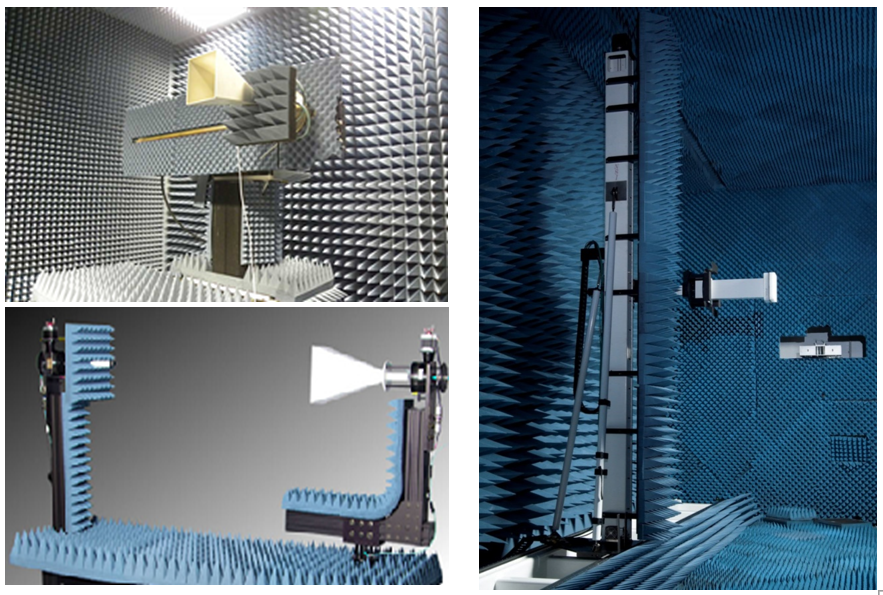
The AUT and receiving antenna are placed apart in the near field, the AUT is placed on a mount that can rotate along the AZ/EL (azimuth/ elevation) axes. The receiving antenna is also capable of moving in the plane along the X, Y and Z axes. The relative motion between the receiving antenna and the AUT results in different scanning methods: planar, cylindrical and spherical scanning.
When to use the measuring chamber?
When the need for accurate measurement and evaluation of the antenna is necessary, building a measurement chamber requires space, equipment, materials, and appropriate budget investment when the antenna to be measured is small in size, and the measurement method used is near-field measurement. The measuring chamber is also more convenient for the operator, monitoring the measurement process, and is not much affected by the weather.
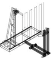
- Planar scanning:
The near-field measurement arrangement for performing flat scanning is depicted in the figure of the sampling step ∆x = ∆y = λ/2. The AUT is fixed. In transmit mode, the probe is moved to scan and sample step by step ∆x, ∆y, up – down/horizontal, on a plane (x,y) parallel to the AUT aperture plane, away from the AUT aperture. from 3λ to 10λ.
The receiving field data will be received by the probe, recorded and then transformed and the probe will be compensated to obtain the far-field emission pattern of the AUT. This is the simplest type of measurement, both in terms of positioning equipment (positioner) and processing software (processing software). The main error encountered in planar measurements is due to the scanning surface not being infinite, leading to errors in the sidelobe structure and limitations in azimuth (truncation error).
This method is often used to measure directional antennas, with G > 15 dBi, the maximum measured azimuth angle is about < ±70 degrees. Depending on the size of the measurement room, array antennas or reflector antennas can be measured.
- Cylindrical scanning:
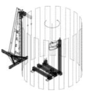
The AUT rotates around the z-axis in ∆φ steps while the probe moves up and down parallel to the z-axis in ∆z steps, creating a scanning journey equivalent to a cylindrical surface surrounding the AUT. The distance between the probe rack and the AUT is chosen to avoid interaction between the AUT and the probe. The length of the cylinder determines the truncation error. The parameters of interest in this method are ∆z = λ/2, ∆φ = λ/2 R; where R is the radius of the cylinder.
This method is suitable for measuring antennas with wide beams (azimuth) with apertures in the range of less than 1.5m.
- Spherical scanning:
There are 2 methods of scanning:
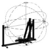
The AUT rotates around the z-axis with steps ∆φ, the probe rotates in a circular orbit around the AUT with steps ∆θ, and the probe remains stationary at a point on the z-axis of the AUT.
The AUT rotates simultaneously around the z-axis and the θ axis in steps ∆φ and ∆θ. The scanning trajectory of the probe is equivalent to that of a sphere of radius R. The scanning angular resolution is ∆φ = ∆θ = λ/2 R rad.
** Advantages of the solution:
- Large measuring range, quick system setup, does not require much labor and time.
- Reasonable cost, simple testing.
- Easy to track, not affected by the weather.
** Disadvantages of the solution
- Request to build or select a space to be an anechoic chamber.
The measurement time is quite long, but the company has data processing solutions that have also optimized the processing and reduced the measurement time.
*** Some practical solutions for 5G antenna testing:

CATR system for 5G small antenna testing
- Internal dimensions (L x H x W): 3.13 x 1.65 x 1.1 m
- Reflector surface: 0.76 x 0.76 m
- Anechoic area: 0.5 x 0.5 m
- Frequency range: 2.4-41 GHz
- Signal blocking coefficient: >20 dB
Ideal for:
- BTS station
- IoT devices
- Antenna for mobile phones
- Antenna for laptop

Spherical Near-field Measurement System
An ideal system for measuring medium and low gain antennas up to 2.0 m (79 in) diameter and is well suited for testing mobile base station antennas.
- Dimensions (L x H x W): Optional x 2.9 x 2.7 m
- Scanning area: Full Spherical; Phi/Theta – 360°
- Maximum antenna load: 136 kg at 23 cm CG offset
- Maximum antenna size: 3.0 m
- Resolution: 0.01° Phi and Theta
- Position repeatability: 0.03° RMS
- Rotation speed: 20°/s Phi, 30°/s Theta
Ideal for:
- Mobile base station antennas

Spherical Near-field Measurement System
The ideal solution is to provide a complete 3D characterization of any antenna or wireless device.
- Dimensions (L x H x W): 3.7 x 4.1 x 3.7 m
- Scanning area: 360° Phi and 330° in Theta°
- Maximum antenna load: 136 kg
- Maximum antenna size: 1.5 m
- Resolution: 0.01° Phi and Theta
- Position repeatability: 0.03° RMS
- Rotation speed: 40°/s Phi, 10°/s Theta
Ideal for:
- IoT devices
- Mobile phone antenna
- Laptop antenna
*Outdoor measuring site:
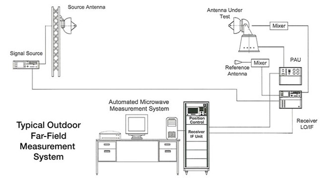
When implementing the outdoor measurement plan, the AUT antenna is installed on a test positioner placed on the top of the tower (or roof, pedestal outside the system equipment control room). The end of the receiver line (the internal oscillator) is usually located below the positioner, with the mixer connected directly to the port of the AUT. The system only requires a single high-frequency path to the positioner, simplifying system setup and operation. The system can be equipped with additional outdoor screens to protect the internal oscillator from weather and extreme temperatures. Multi-port antennas can perform simultaneous measurements using a multiplexer installed before the mixer. The receiver and transmitter positions are controlled through the receiver interface.
The transmitting antenna (source) is placed opposite the receiving tower, ensuring the receiving side receives the signal. The signal source is placed near the transmitting antenna to reduce signal loss. Control communication between the transmitter and receiver sides is performed by fiber optic cable or Ethernet.
When to build an outdoor measuring site?
Outdoor measuring sites require a more complex and long-term deployment process. Of course, the efficiency of the measurement is also greatly improved, especially the practicality of the measurement, because the outdoor measurement system can measure many types of AUT antennas in different measurement ranges and sizes, huge antennas such as radar antennas, phased array antennas… In addition, outdoor measurement sites also provide more realistic results due to the influence of environmental factors during the measurement process.
Typical parameters:
- Frequency range: full frequency range supported by high-frequency devices
- Control system: stepper motor or servo motor
- Maximum antenna load: flexible, depending on requirements
- Position resolution: 0.01°
- Rotation speed: 40°/s
- Measuring system: measuring control workstation with LCD control screen
- Motor cable: Quick-connect; 40′ (12.2m)
- High frequency cable: ~6.1m; DC-18 GHz; SMA or N connection
Deployment plan
The reference antenna (source antenna) and the AUT antenna are arranged on high towers, ensuring the following distance and height requirements:
- Distance between reference antennas and AUT: r > 2D2/λ;
- Height of hAUT towers = hAS > 4D (where D is the vertical dimension of the AUT) to ensure reflections are minimized.
- Dimension d of reference antenna: d < 0.37 λR/D
To ensure amplitude taper at the AUT surface and reflected noise due to the environment, the first null point is required to be lower than the base of the antenna. If you want to reduce reflections further, you can use range fences.
** Advantages of the solution
- Wide measuring range, can measure many types of antennas.
- Measurements are performed quickly, and the measurement results are very close to reality.
- High professionalism and excellent reliability of results.
** Disadvantages of the solution
- Large cost and lengthy implementation time to ensure technical and project quality.
- Physically affected by weather and climate; however, there are solutions to protect the project.
4. List of investment equipment
Please get in touch with us for more detailed information about the solution.
Our company always wishes to become a reliable partner and a leading supplier of equipment and solutions for the success of our customers. For more detailed information, please contact:
MITAS Hanoi Technology JSC
Address: 5th Floor, C’Land Building, No. 81 Le Duc Tho St., My Dinh 2 Ward, Nam Tu Liem Dist., Hanoi, Vietnam
Web: https://mitas.vn | Tel: (+84) 243 8585 111 | Email: sales@mitas.vn
The trust and support of our customers are a driving force and an invaluable asset to our company. We sincerely thank you./.
